Horizontal Plate Filter

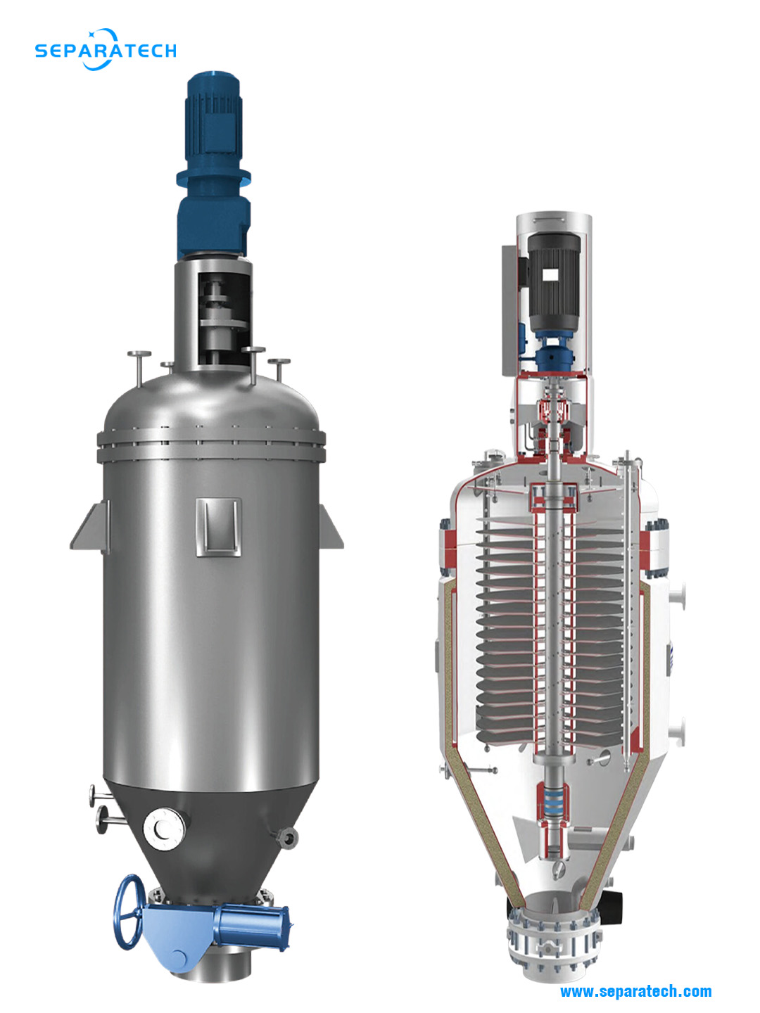
The horizontal plate filter is a centrifugal discharge, pressure leaf filter. It is compact, enclosed, self-cleaning, multi-plate filters available with integrated heating and drying for manufacturing, pilot and laboratory applications.
The top or bottom mounted drive assembly can be easily removed from the vessel. Options include hydraulic drive, electric drive with variable speed drive system.
The seal and bearing assembly are designed to eliminate causes of failure, the seal rides on a bearing sleeve instead of the shaft, pre-venting shaft wear and potential for costly repair. Seal options include lip seals, stuffing box (with or without flushing), mechanical seal or hydraulic bellows seal.
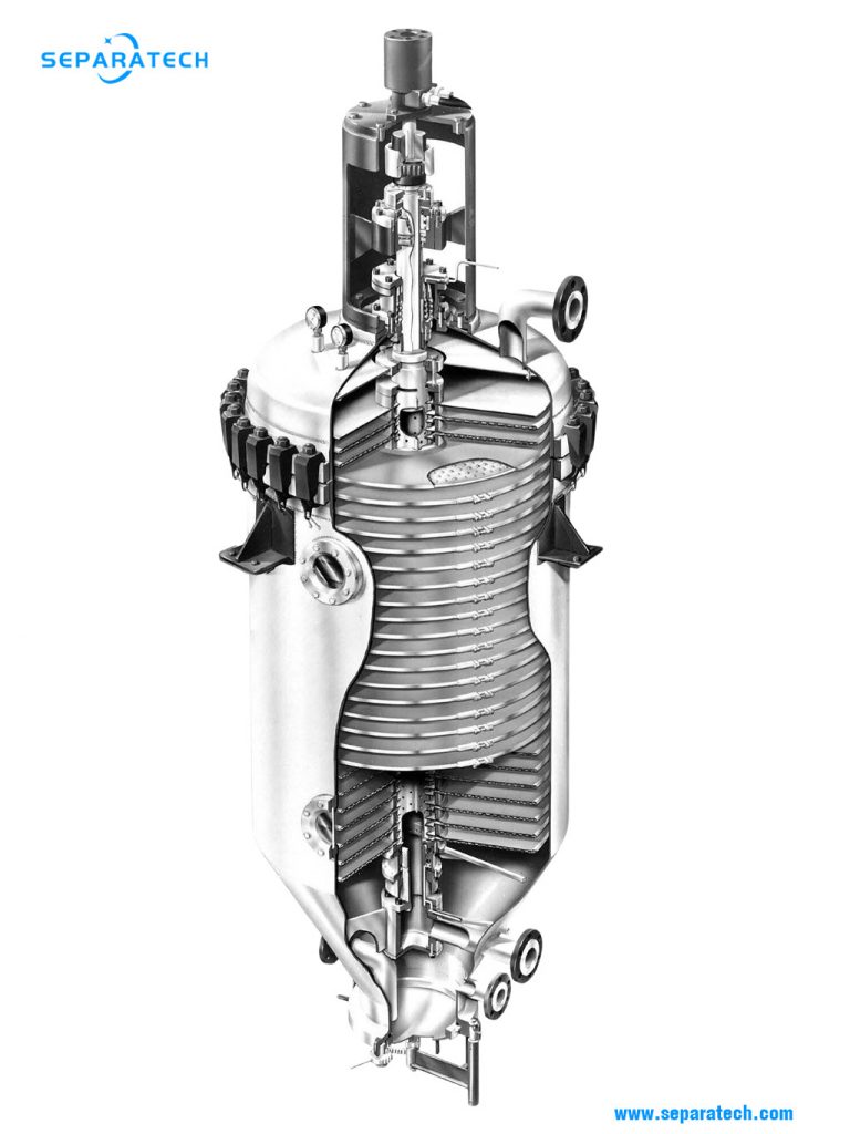
Horizontal dished filter plates with spacer rings and sealing gaskets are mounted on a hollow shaft, and secured by a tightening device. The filter media is held in place by a clamp ring and can be quickly and easily changed. Various types of media are available.
FDT is designed for the discharging of dry filter cake. FDB series is designed for discharging of slurry filter cake.
Applications
The closed self-cleaning horizontal plate filter for the separation of solids from liquids can be used fully automatic in batch, as well as continuous processes. For use in continuous processes, two filters are required which alternately filtrate and regenerate.
Horizontal plate filters have been widely used in various industrial sectors such as:
– Environmental protection:
horizontal plate filters are used for wastewater treatment, sludge conditioning, waste processing and soil remediation.
– Food:
horizontal plate filters are used in the production of sugar, starch, gelatin, yeast, dairy, beverages and other foods.
– Pharma:
horizontal plate filters are used to manufacture antibiotics, hormones, vitamins, vaccines and other pharmaceutical products.
– Chemistry:
horizontal plate filters are used in the manufacture of dyes, pigments, resins, plastics, catalysts and other chemical products.
– Nuclear:
horizontal plate filters are used to treat radioactive waste and recover valuable nuclides.
– Hydrometallurgy:
horizontal plate filters are used to recover metals from ores or solutions.

Main structure
Filter Vessel
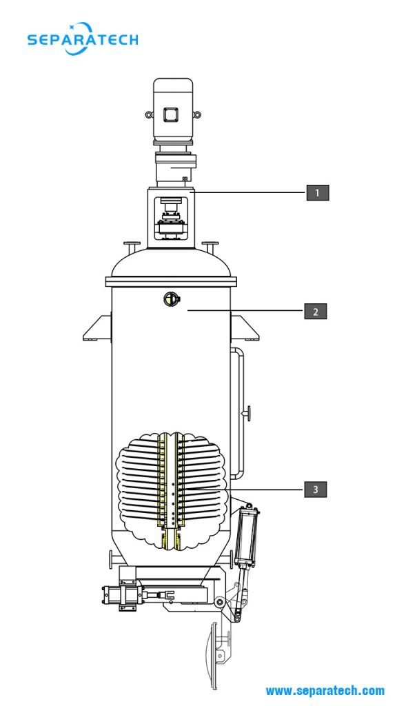
The largest part of the horizontal plate filter is the vessel. The head, which is removable, closes the top of the vessel and supports the filter plates and the drive unit. The head of the larger vertical vessels is often pivoted so that it is swung away to allow the upwards removal of the plates stack. The layout should provide sufficient headroom for raising the stack over the vessel and additional floor space next to the filter for stack maintenance and replacement of damaged plates. The filter vessel might be supplied with a heating or cooling jacket, brackets or legs being provided for erection.
The vessels at their bottoms are fitted with highly secured cake discharge openings to ensure safe sealing of the tank under pressure.
The pressure vessels are constructed according to the respective acceptance regulations such as TUEV, PED, ASME, China Stamp, GOST, SVTI, etc. Depending on the corrosion esistance, the materials extend from HII to stainless steel, Hastelloy and titanium; rubber lined constructions are also available.
Filter plate
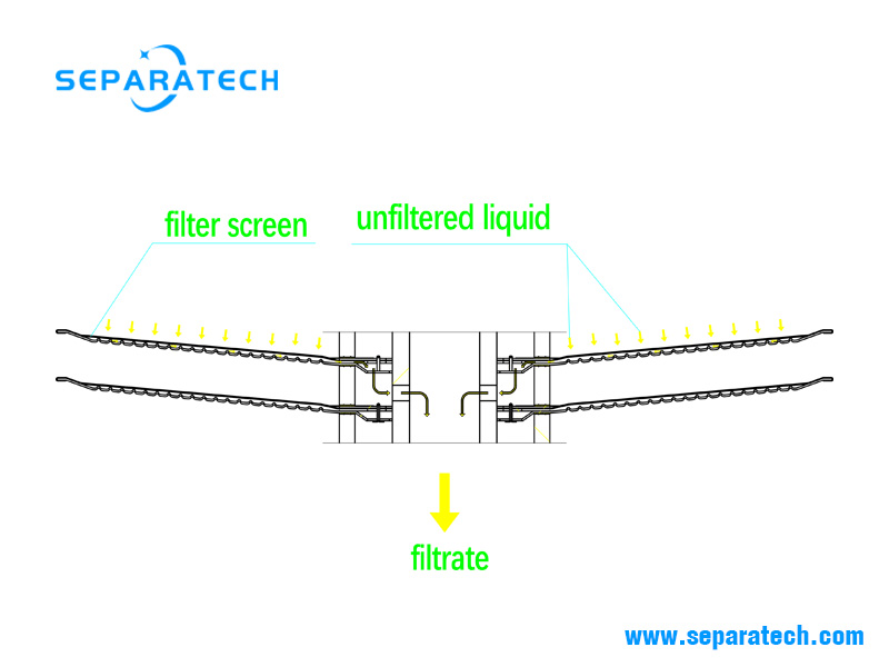
Each filter plate assembly consists of a filter plate, a support screen, a filter screen and an outer clamp ring. There is also a passage ring and an inner clamp ring. The inner and outer clamp rings hold the filter screen in place while the support screen and the passage ring are trapped between the filter screen and the filter plate. The filter plates with the spacer rings and gaskets piled up to a filter stack on the hollow shaft are tightly tensioned against the filter shaft support under the lowest plate, whereas the top plate is a non-filtering flow protection plate. Due to the slightly conical shape of the plate, the complete draining of liquid is ensured.
The cross-section shows the arrangement of the individual elements such as the filter screen, support screen, clamp ring, dimpled plate, passage ring and gaskets.
Filter drive
The filter drive can be either electric or hydraulic. The hydraulic drive is directly coupled to the filter shaft while the electric drive employs a reducer. When the electric drive motor is mounted vertically above the filter shaft, a gear reducer is installed. The electric drive option uses a programmable VFD speed controller.

Working principle
Unfiltered liquid is pumped into the vessel and flows around the stationary filter plates. When the vessel is full, the pres-sure in the vessel begins to rise. This pressure forces the unfiltered liquid through the filter screens. The solids are left on the filter plates and the filtered liquid flows into the hollow shaft to drain out through the filtrate outlet which exits through the bottom of the vessel. The filter nest re-mains stationary during filtration. Once the filter is empty, the filter plates briefly spins at high speed to sling off the cake. The cake falls to the bottom of the vessel from where discharged out of the filter.

Operational sequence
The horizontal plate filter can be operated manually, semi-automatically or automatically. All of the capabilities of modern control technology can be used until the point of integration into control systems with a link to the production control.
Precoating
The precoating stage is done only in the following cases:
-When the contaminants are gelatinous and sticky it forms a barrier that avoids cloth blinding. Likewise, the interface between the precoat and the cloth departs readily so the cake discharges leaving a clean cloth.
-When a clear filtrate is required immediately after the filtration cycle commences otherwise recirculation must be employed until a clear filtrate is obtained.
Filtration
Once the precoating stage is completed the process slurry is pumped into the filter, the forming cake is retained on the plates and the filtrate flows to further processing.
When the solids are fine and slow to filter a body-aid is added to the feed slurry in order to enhance cake permeability. However, it should be kept in mind that the addition of body-aid increases the solids concentration in the feed so it occupies additional volume between the plates and increases the amount of cake for disposal.
Likewise, for all those applications when the cake is the product, precoat and filter-aid may not be used since they mix and discharge together with the cake.
Please refer to the section on Pressure Filters for further details on precoating and the addition of body-aid.
Heel Removal
Once the filtration cycle is completed air or gas is blown into the vessel and the slurry heel that surrounds the plates is pushed and displaced downwards until it reaches the lowest part of the plate stack. At this point the remaining heel slurry is evacuated back to the feed tank by a special dip pipe that is located at the very bottom of the vessel so that the vessel is empty from slurry.
Cake Drying
The air then continues to pass through the cake until the captive moisture is reduced to a minimum and the cake is in practical terms considered to be dry.
Cake Discharge
At this point the air pressure is released, the cake outlet is opened and the plate stack is rotated to discharge the cake. The cake outlet opening must be interlocked with the motor drive since its spinning is conditional to the outlet being open.
On some filters the cloth or mesh screen may backwashed with water after cake discharge to dislodge and remove any cake residue that adhered to the medium.
Technicial parameters
| Designations | Filtration area (m2) | Plate diameter (mm) | Working temp. (°C) | Working pressure (Mpa) | Dimensions (mm) |
|---|---|---|---|---|---|
| FDT-2 | 2 | 500 | 150 | 0.4 | 700*2600 |
| FDT-5 | 5 | 650 | 150 | 0.4 | 800*3800 |
| FDT-7 | 7 | 800 | 150 | 0.4 | 1000*3700 |
| FDT-10 | 10 | 800 | 150 | 0.4 | 1000*3800 |
| FDT-12 | 12 | 800 | 150 | 0.4 | 1000*4200 |
| FDT-15 | 15 | 1000 | 150 | 0.4 | 1200*4400 |
| FDT-20 | 20 | 1000 | 150 | 0.4 | 1200*4600 |
| FDT-25 | 25 | 1000 | 150 | 0.4 | 1200*5200 |
| FDT-30 | 30 | 1000 | 150 | 0.4 | 1200*6000 |
| FDT-35 | 35 | 1200 | 150 | 0.4 | 1400*6800 |
| FDT-40 | 40 | 1200 | 150 | 0.4 | 1400*7500 |
| FDT-45 | 45 | 1200 | 150 | 0.4 | 1400*8200 |
| FDT-50 | 50 | 1200 | 150 | 0.4 | 1400*8900 |
| FDT-60 | 60 | 1200 | 150 | 0.4 | 1400*1000 |
| Designations | Filtration area (m2) | Plate diameter (mm) | Working temp. (°C) | Working pressure (Mpa) | Dimensions (mm) |
|---|---|---|---|---|---|
| FDB-2 | 2 | 500 | 150 | 0.4 | 900×1480 |
| FDB-5 | 5 | 700 | 150 | 0.4 | 1200×2050 |
| FDB-7 | 7 | 700 | 150 | 0.4 | 1200×2050 |
| FDB-10 | 10 | 850 | 150 | 0.4 | 1600×2900 |
| FDB-15 | 15 | 850 | 150 | 0.4 | 1600×3100 |
| FDB-20 | 20 | 1000 | 150 | 0.4 | 2200×3200 |
| FDB-25 | 25 | 100o | 150 | 0.4 | 2200×3480 |
| FDB-30 | 30 | 1220 | 150 | 0.4 | 2300×3400 |
| FDB-35 | 35 | 1220 | 150 | 0.4 | 2300×3800 |
| FDB-40 | 40 | 1220 | 150 | 0.4 | 2300×4100 |
| FDB-45 | 45 | 1220 | 150 | 0.4 | 2300×4500 |
| FDB-55 | 55 | 1220 | 150 | 0.4 | 2300×4800 |
| FDB-65 | 65 | 1220 | 150 | 0.4 | 2300×2100 |