Clarifying Decanter Centrifuge
Clarifying decanter centrifuge is mainly designed for separating solids from liquid phase. Including dewatering process for maximum concentration of solids, or concentrating solids phase.

Working principle of Clarifying Decanter Centrifuge
Solids-liquid Separation takes place in a horizontal cylindrical bowl equipped with a screw conveyor. The raw material is fed into the decanter centrifuge bowl through a inlet tube and is then smoothly accelerated by an inlet rotor. Centrifugal force immediately makes the solids build up on the wall of the bowl. The scroll conveyor rotates in the same direction as the bowl, but at a different speed, thus moving the solids towards the conical end of the bowl. The solids leave the bowl through the solids discharge openings into the casing. Centrifugal separation takes place throughout the entire length of the cylindrical part of the bowl, and the clarified liquid leaves the bowl by flowing over adjustable plate dams into the casing. In some cases, cleaned liquid phase is discharged out under pressure through built-in impeller.
Basic Construction of Clarifying Decanter Centrifuge
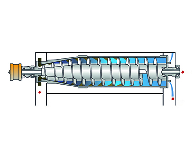
The construction of a basic centrifuge with all its main components is shown in the above figure. The heart of the decanter is the rotating assembly, which comprises a mainly cylindrical bowl housing an Archimedian screw conveyor, with a small clearance between it and the bowl. One end of the bowl is conical in shape, providing the means whereby solids can be removed from it. Affixed to one end of the bowl is usually a gearbox to effect a small differential speed between the conveyor and bowl.
The rotating assembly, usually horizontal, is supported by a bearing in a pillow block at either end of the assembly. Surrounding the bowl is a casing to collect at one end the clarified liquor and dewatered cake at the other. The bearing pillow blocks are mounted accurately on a rigid frame together with the casing.
Sometimes the frame is mounted on a sub-frame together with the drive motor, and where necessary a back-drive system, to control the gearbox pinion shaft. which will in turn control the conveyor-to-bowl differential speed. The back-drive system will be described further, but for the present it suffices to say that it is essentially a braking motor or similar device coupled to the gearbox pinion shaft. The main motor is offset from the bowl and drives the bowl by means of a set of V-belts. The back-drive can also be offset. In which case it would be connected with a timing belt. The timing belt is to facilitate more accurate speed control. However, the back-drive system can also be mounted direct in line with the pinion of the gearbox.
The sub-frame assembly, or the main frame if there is not a sub-frame, usually is supported by vibration isolators.
The feed enters the bowl through ports in the conveyor, having entered the conveyor hub through a stationary coaxial feed tube projecting into the conveyor from a support, mounted on the main frame.
Feed slurry is metered through the feed tube into the rotating bowl. Suspended solids sediment to the bowl wall, where they are picked up by the conveyor and scrolled as a saturated cake to the conical end of the bowl, over the heel of cake which builds up in the small clearance between the bowl and conveyor. The resulting clarified liquor flows to the opposite end of the bowl and decants over weirs into the casing for discharge. The cake scrolls up the conical section of the bowl, the beach, before it falls into the casing for discharge.
The heel, the thin layer of process solids which builds up between bowl and conveyor, can progressively consolidate with coarser particles bedding themselves into it. This, while providing an aid to scrolling efficiency, can be an unwanted source of abrasion for the conveyor. However, generally, there is a tendency for the heel to move, albeit at a much lower rate than the cake itself. Thus there is a tendency for the heel slowly, but continuously, to regenerate itself.
Materials of construction are important considerations in the basic design. Most decanters are constructed with the parts in contact with the process in some form of stainless steel.